
I. Flexible Protective Net Design Specifications
1、SNS flexible protective mesh design considers safety.
When selecting materials from a height, the primary concern is the safety of all users, including adults and children, as the entire landscape is accessible to residents. Therefore, the minimum height should be at least 1.1 meters above the existing level, providing adequate protection for both adults and children.From a materials and durability perspective, the selected materials must effectively ensure the safety of personnel and vehicles, meeting the required lifespan. This comprehensive consideration should also factor in local environmental conditions and budget constraints.
2、SNS flexible protective mesh should also consider the aesthetic aspect.
The design of this protective net should fully consider the width or depth of the river, as well as the compatibility with the railings, in order to achieve a layered aesthetic effect. Furthermore, from the perspective of the color and structure of the railing, it should be able to harmonize with the surrounding environment.
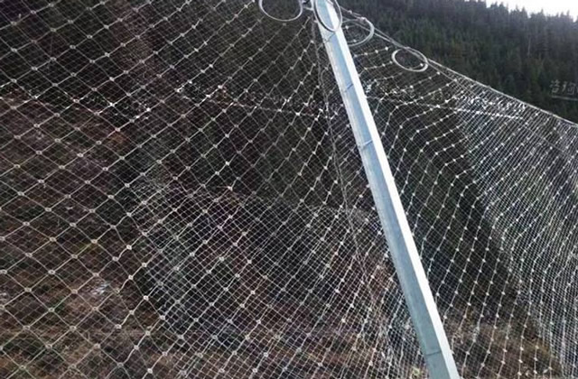
II. Construction Plan for Flexible Protective Netting
1、 Slope cleaning
In most cases, slope leveling is not necessary, but the following two situations require consideration:
When there is loose soil or loose rock on the slope, especially in areas where construction personnel are working, it is advisable to remove or temporarily treat the loose material to prevent collapses or falling debris that could endanger construction safety.
For individual, isolated, and potentially unstable rock faces on slopes that pose a high risk of collapse, and where the resulting collapse could necessitate extensive maintenance work exceeding the system's protective capacity, appropriate reinforcement or pre-removal should be considered.
2、Unwinding
While standardized anchor rod positions and other dimensional constraints exist, there is also a certain allowance for adjustments, particularly for anchor rods, which offer greater flexibility in placement. Furthermore, the on-site conditions themselves are often complex and may not be fully reflected in the design drawings, especially in details that can be utilized or require special attention. String measurements are used to determine the anchor hole positions (with a tolerance of 0.3m for spacing, depending on the terrain conditions).
3、Foundation Construction
This work primarily aims to ensure the anchoring capacity of the anchor bolts. Specifically, for anchor bolt holes drilled in locations where the substrate is bedrock or hard rock, and for loose soil conditions where direct hole drilling is not feasible, excavation of the pit or concrete foundation pouring may be required. After drilling the anchor bolt holes to the specified depth, which should be at least 5cm longer than the designed anchor bolt length, and with a diameter not less than φ38-42mm, clean the holes. When equipment limitations restrict the drilling process, two steel ropes can be anchored into two holes with a diameter not less than φ35 each, forming a "V" shaped anchor. The angle between the two ropes should be 15°~30° to achieve the same anchoring effect.
4、Anchor rod installation
For anchor bolts installed using the direct bored method, the anchor bolts are installed by pouring concrete. For anchor bolts installed in concrete foundations, the anchor bolts are typically embedded directly during the pouring of the foundation concrete. After injecting concrete and inserting the anchor bolts (ensuring that the outer edge of the anchor bolt and the top of the sleeve do not exceed the ground surface, and that the sleeve section cannot be injected with concrete to ensure that the support rope can be as close to the ground surface as possible after tensioning), use a concrete mix with a minimum strength of M20. The concrete inside the hole should be completely filled. The injected concrete must be cured for at least three days before proceeding to the next stage of work.
5、Install support ropes
Install transverse and longitudinal support ropes, and tighten them. Secure each end with 2~4 rope clips and exposed anchor rod loops (use 2 clips and loops when the rope length is less than 15m, and 4 clips and loops when the rope length is greater than 30m, with 3 clips and loops in between).
Lay the grating mesh from top to bottom. The overlap width between grating meshes must not be less than 5 cm. The joints between two grating meshes and the connection between the grating mesh and the support rope should be secured with φ1.2 iron wire at a spacing of 1m (if possible, this step can be completed before the previous step, placing the grating mesh under the support rope).
6、Installation of grating
Install grating mesh from top to bottom. The overlap width between grating meshes should not be less than 5 cm. The joints between two grating meshes and the connections between the grating mesh and the support ropes should be secured with φ1.2 iron wire at a spacing of 1m (if possible, this step can be completed before the previous step, placing the grating mesh below the support ropes).
7、Mounting and stitching of steel mesh
Lay and stitch the steel wire mesh from top to bottom, using φ8 steel wire for the stitching. Each steel wire mesh is stitched to the surrounding support wires using a stitching wire approximately 31m (or 27m) long. The ends of the stitching wire are fixed to the mesh wires using two wire clips.
8、Comprehensive Work Process
After the system is installed, it is advisable to use soil or small stones to press the grating laid on the ground, where possible, to prevent stones from lifting the grating upwards.